Beams are the backbone of buildings.
They carry loads from slabs and walls.
They transfer those loads to columns and foundations.
Good beam reinforcement detailing keeps the structure safe.
It also saves material, reduces cracks, and makes construction faster.
This article explains beam reinforcement in clear, simple English.
Short sentences improve readability.
You’ll get design rules, shop and site detailing, bar bending schedule (BBS) tips, IS-code notes, and practical checks for Indian projects.
Tables make quick facts easy to use.
Why Good Beam Reinforcement Detailing Matters
Correct detailing makes beams behave as designed.
It controls bending, shear, and torsion.
It controls cracking and deflection.
It helps during earthquakes and heavy loads.
Bad detailing causes weak joints, corrosion, and costly repairs.
Designers must follow IS 456 and supporting guides for safe detailing.
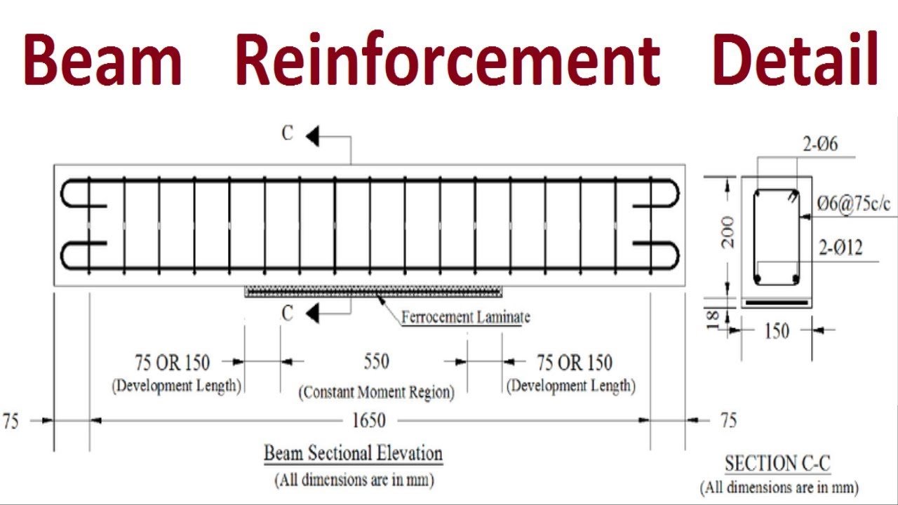
Basic Reinforcement Layout of a Rectangular Beam
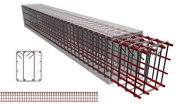
A typical simply supported beam uses:
- Top bars — resist negative moments (over supports) or compression in continuous beams.
- Bottom bars (tension bars) — resist positive bending at midspan. These are the main tensile bars.
- Stirrups / links — closed or U-shaped ties that resist shear and hold bars in position.
- Distribution bars — control cracking and distribute loads across the breadth.
- Hooks and development — bends and hooked ends that help anchor bars into concrete.
A drawing usually shows top and bottom layers, stirrup spacing, and cover. Keep nominal cover as per IS 456.
Minimum and Typical Reinforcement Percentages
IS 456 gives guidance for minimum steel in beams to avoid brittle failure.
A simplified formula:
Ast,min = 0.85 / fy × b × d
(where fy is yield strength in MPa, b is width, and d is effective depth)
Practical approximate minimums:
| Steel Grade | Approx. Min. % of Gross Area |
|---|---|
| Fe 250 | 0.34% |
| Fe 415 | 0.205% |
| Fe 500 | 0.17% |
Do not overconcentrate steel in one layer. Spread bars so concrete covers and vibrates properly.
Bar Sizes & Selection (Practical)
- Common bar diameters: 8 mm, 10 mm, 12 mm, 16 mm, 20 mm, 25 mm, 32 mm.
- Use smallest practical diameter to control crack spacing.
- Use 16 mm or 20 mm as main bars in residential beams.
- Large bars (≥ 36 mm) are discouraged for lapped joints; use welds or mechanical splices instead.
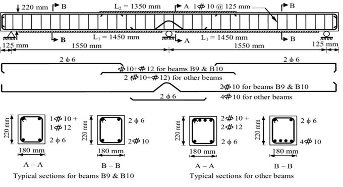
Stirrups / Links — Spacing and Shape
Stirrups prevent shear failure and confine compression zones.
- Use closed stirrups wherever possible.
- Near supports, provide closer spacing: 75–100 mm.
- At midspan, spacing can be 150–200 mm for ordinary loads.
- Hooks should be 135° with 9d length (where d = bar diameter).
- Max spacing: 0.75d for shear zone or 300 mm, whichever is less.
Also Read Plastic Roads in India: Turning Waste into Stronger Roads for a Sustainable Future
Development Length (Ld) — Anchorage to Develop Bar Strength
Development length is the length needed to transfer stress into concrete by bond.
- Larger diameter bars need longer Ld.
- For Fe415 and Fe500, IS 456 allows adjustments to bond stress.
- A practical guide: 40–60 × bar diameter for anchorage in flexural zones (verify with code formula).
Lap Splices — Where and How Long
- Avoid splicing near points of maximum moment.
- If splicing is necessary, stagger the laps and add confinement.
- Lap length ≈ development length and not less than 30d for flexural tension.
- For direct tension, lap ≈ 2 × Ld.
- Bars above 32–36 mm should be welded or mechanically spliced.
Hooks, Bends and Anchorage Details
- Use 90° or 135° hooks depending on location.
- Standard 135° hook length = 9 × bar diameter.
- Avoid sharp bends; use standard radii.
- Good anchorage prevents slippage and improves ductility.
Shear Reinforcement for Various Beam Types
- Simply supported beams: maximum shear near supports — closer stirrups in end zones.
- Continuous beams: shear pattern differs — add stirrups at supports.
- T-beams: ensure stirrups pass through the web.
- Deep beams: may require strut-and-tie approach.
Torsion — When to Detail for It
- Eccentric or curved beams may face torsion.
- Provide closed stirrups and longitudinal reinforcement in both faces.
- Follow IS 456 for combined bending, shear, and torsion checks.
Serviceability — Crack Width, Spacing, and Deflection
- Use smaller diameter bars to control crack width.
- Provide distribution reinforcement to control shrinkage cracks.
- Follow span/depth ratios for deflection limits.
- Ensure proper cover for durability: 20 mm (slabs), 25 mm (beams).
Bar Bending Schedule (BBS) — Best Practice
Include:
- Bar mark and location.
- Diameter and grade.
- Cut length (with bends/hooks).
- Number of bars and total weight.
Use spreadsheets or software to reduce errors and waste.
Seismic Detailing for Ductility
In seismic zones:
- Provide hooped ties around bars in critical regions.
- Confine column-beam joints with closer stirrups.
- Avoid laps in plastic hinge zones.
Common Site Mistakes to Avoid
- Wrong cover — always use proper cover blocks.
- Loose bars — tie firmly with binding wire.
- Incorrect lap location — avoid lapping in high moment zones.
- Inadequate hook length — follow standard 9d rule.
Quick Reference Table — Cover and Spacing
| Item | Nominal Cover (mm) | Stirrup Spacing |
|---|---|---|
| Slab beam top/bottom | 20–25 | — |
| Beam face cover | 25 | — |
| Column-beam joint cover | 40 | — |
| Stirrup spacing (supports) | — | 75–100 mm |
| Stirrup spacing (midspan) | — | 150–200 mm |
Quality Checks Before Concreting
- Cover blocks fixed.
- Bars tied and supported.
- Stirrups correctly oriented.
- Splices staggered.
- BBS verified.
FAQs
Q1: What is the minimum bottom reinforcement for a simply supported beam?
A: Use IS 456 formula — Ast,min = 0.85 / fy × b × d.
Q2: Where should lap splices be avoided?
A: Avoid in maximum moment or plastic hinge zones.
Q3: How close can stirrups be near supports?
A: 75–100 mm, depending on shear design.
Q4: How long is a 135° hook?
A: 9 × bar diameter (9d).
Q5: Should I use fewer thick bars or more small bars?
A: More smaller bars are better for crack control and workability.
Conclusion — Practical Takeaways
Beam reinforcement details are the link between design and durability.
Follow IS 456 and SP 34 for correct detailing.
Pay special attention to anchorage, lap length, shear reinforcement, and seismic safety.
Good detailing ensures strength, saves materials, and avoids costly repairs.